- 您现在的位置:买卖IC网 > Sheet目录509 > SI4322-A0-FT (Silicon Laboratories Inc)IC RX FSK UNI 868/915MHZ 16TSSOP
Si4322
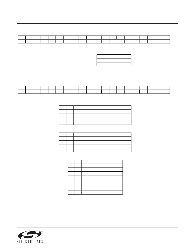
Frequency Setting Command
bit
15
1
14
0
13
1
12
0
11
f11
10
f10
9
f9
8
f8
7
f7
6
f6
5
f5
4
f4
3
f3
2
f2
1
f1
0
f0
POR
AD57h
The 12-bit Frequency Setting Command < f11 : f0 >
has the value F. The value F should be in the range
The constant C is determined
by the selected band as:
of 96 and 3903. When F is out of range, the
previous value is kept. The synthesizer center
frequency f 0 can be calculated as:
f 0 = 8 * 10 MHz * (C + F/4000)
Receiver Setting Command
Band [MHz]
868
915
C
10
11
bit
15
1
14
1
13
0
12
0
11
0
10
0
9
0
8
0
7
d1
6
d0
5
g1
4
g0
3
r2
2
r1
1
r0
0
en
POR
C080h
Bit 7-6 < d1:d0 >:
Select the VDI (valid data indicator) signal:
Bit 5-4 < g1:g0 >:
d1
0
0
1
1
Set the LNA gain:
g1
0
0
1
1
d0
0
1
0
1
g0
0
1
0
1
VDI output
Digital RSSI Out (DRSSI)
Data Quality Detector Output (DQD)
Clock recovery lock
Always
G LNA (dB relative to max. G)
0
-6
-12
-18
Bit 3-1 < r2:r0 >:
Control the threshold of the RSSI detector:
r2
0
0
0
0
1
1
1
1
r1
0
0
1
1
0
0
1
1
r0
0
1
0
1
0
1
0
1
RSSIsetth [dBm]
-103
-97
-91
-85
-79
-73
-67
-61
The RSSI threshold depends on the LNA gain, the real RSSI threshold can be calculated:
RSSI th = RSSI setth + G LNA
Bit 0 < en >:
the low
Enables the whole receiver chain and crystal ocsillator when set. Enable/disable of the wake-up timer and
battery detector are not affected by this setting.
10
发布紧急采购,3分钟左右您将得到回复。
相关PDF资料
SI4324DY-T1-GE3
MOSFET N-CH D-S 30V 8-SOIC
SI4330-B1-FM
IC RCVR ISM 960MHZ 3.6V 20-QFN
SI4354DY-T1-GE3
MOSFET N-CH D-S 30V 8-SOIC
SI4355-B1A-FM
IC EZRADIO FM RECEIVER SI4355
SI4388DY-T1-GE3
MOSFET DUAL N-CH 30V 8-SOIC
SI4390DY-T1-GE3
MOSFET N-CH 30V 8.5A 8SOIC
SI4396DY-T1-GE3
MOSFET N-CH D-S 30V 8-SOIC
SI4398DY-T1-GE3
MOSFET N-CH 20V 19A 8-SOIC
相关代理商/技术参数
SI4322-A0-FTR
功能描述:射频接收器 Receiver (EZRadio) RoHS:否 制造商:Skyworks Solutions, Inc. 类型:GPS Receiver 封装 / 箱体:QFN-24 工作频率:4.092 MHz 工作电源电压:3.3 V 封装:Reel
Si4322-A1-FT
功能描述:射频接收器 RECEIVER EZRadio UNIVRSL ISM BAND FSK RoHS:否 制造商:Skyworks Solutions, Inc. 类型:GPS Receiver 封装 / 箱体:QFN-24 工作频率:4.092 MHz 工作电源电压:3.3 V 封装:Reel
SI4322DY-T1-E3
功能描述:MOSFET 30V 18A 5.4W 8.5mohm @ 10V RoHS:否 制造商:STMicroelectronics 晶体管极性:N-Channel 汲极/源极击穿电压:650 V 闸/源击穿电压:25 V 漏极连续电流:130 A 电阻汲极/源极 RDS(导通):0.014 Ohms 配置:Single 最大工作温度: 安装风格:Through Hole 封装 / 箱体:Max247 封装:Tube
SI4322DY-T1-GE3
功能描述:MOSFET 30V 18A 5.4W 8.5mohm @ 10V RoHS:否 制造商:STMicroelectronics 晶体管极性:N-Channel 汲极/源极击穿电压:650 V 闸/源击穿电压:25 V 漏极连续电流:130 A 电阻汲极/源极 RDS(导通):0.014 Ohms 配置:Single 最大工作温度: 安装风格:Through Hole 封装 / 箱体:Max247 封装:Tube
SI4324DY-T1-E3
功能描述:MOSFET 30V 36A 7.8W RoHS:否 制造商:STMicroelectronics 晶体管极性:N-Channel 汲极/源极击穿电压:650 V 闸/源击穿电压:25 V 漏极连续电流:130 A 电阻汲极/源极 RDS(导通):0.014 Ohms 配置:Single 最大工作温度: 安装风格:Through Hole 封装 / 箱体:Max247 封装:Tube
SI4324DY-T1-GE3
功能描述:MOSFET 30V 36A 7.8W 3.2mohm @ 10V RoHS:否 制造商:STMicroelectronics 晶体管极性:N-Channel 汲极/源极击穿电压:650 V 闸/源击穿电压:25 V 漏极连续电流:130 A 电阻汲极/源极 RDS(导通):0.014 Ohms 配置:Single 最大工作温度: 安装风格:Through Hole 封装 / 箱体:Max247 封装:Tube
SI4330-A0-FM
功能描述:射频接收器 Receivers - IA4330 RoHS:否 制造商:Skyworks Solutions, Inc. 类型:GPS Receiver 封装 / 箱体:QFN-24 工作频率:4.092 MHz 工作电源电压:3.3 V 封装:Reel
SI4330-B1
制造商:SILABS 制造商全称:SILABS 功能描述:Si4330 ISM RECEIVER
